|
|
| Owner |
Alan Grant |
| Location |
California, USA |
| email |
whsagrant@yahoo.com |
| Web Page |
- |
| Year |
- |
| Car |
Mirage |
| Color |
red |
| Builder |
- |
| Chassis Type |
tube |
| Chassis Number |
216 |
| Engine Make |
- |
| Displacement |
- |
| Transmission/Transaxle |
- |
| HP |
- |
| Front Suspension |
|
| Rear Suspension |
Corvette |
| Steering |
- |
| Interior |
- |
| Notes |
Body & frame 216 sat in garages, storage spaces, for around 20 years, waiting for construction to start. Sometimes the dust was removed, the frame was painted, or the body was waxed. Then it was sold to the second owner, me, on March 6, 1999 to languish in the dark for another six years. Suddenly things changed, there was a new garage, a new fixture to hold the frame, and the body parts were getting measured for fitting.
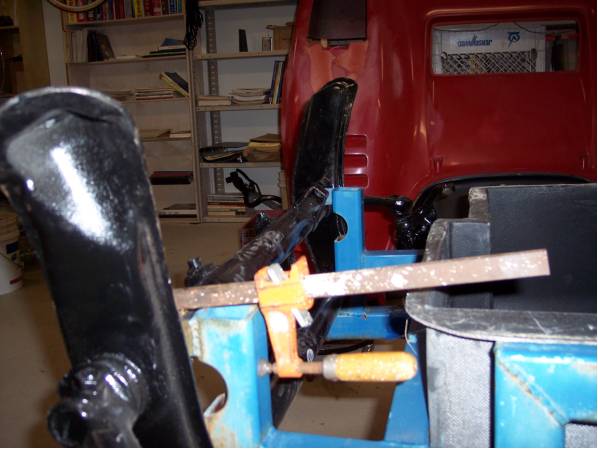
I was ready for the adventure in car construction to begin! I started to connect the new ball joint front end with disc brakes to the frame. It does not fit! The frame was all set for the VW link pin front end but I had purchased a ball joint front end, with disc brakes. Seems the ball joint front-end torsion tubes are one and one sixteenth inch farther apart than the link pin tubes. First rule of car construction, a simple change is really a complex change. So the mounts were cut in half, vertically lengthened, and welded into the new position. Now the tubes fit, but will use a new way of holding in the front end using the dune buggy clamps.
Nothing was square on the frame, except the square where the Driver's Butt (DB) resides in the car. Using my favorite construction adventure tools, the Harbor Freight $10 Laser Level, the measuring tape and a plumb bob, (Is there a motto like that?) laid out a centerline from DB to mark the front-end centerline. Using the new centerline from the front-end and targeting the butt point centerline allowed the centerlines to be marked on the other cross-members.
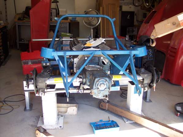
The rear suspension got new adjustable strut rods from the Corvette people, because I have had bad experiences with the Adjuster Cams moving when it is the worst moment. The strut rods were the appropriate length, but the bolt mounting holes need to be enlarged. The angles of the drive shaft compared to the strut rod, caused large camber changes as the wheel goes up and down. The solution was a new mount on the transaxle from Clark's Corvair Parts that lowered the strut rod mounting points, decreasing the camber gain, a lot.
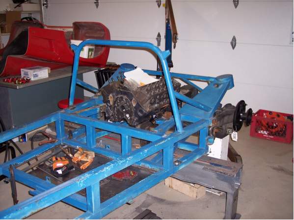
The engine would not sit centered in the car, so the mounts were cut off, simple, drastic, and I'll find out the consequence soon enough. The drive-shafts, hubs, differential, were not in line or centered. The rear suspension was connected to the frame and a string run from hub center-line to hub center-line. It did not line up, passenger side was Ľ Inch short, or that was my guess, so in goes a Ľ Inch plate to lengthen it into square position. Next, the engine was centered in the frame while the transaxle is centered fore and aft on the axle hub centerlines. Weld those motor mounts into place! Progress! Put those drive shafts in and then we will . . . What do you mean they do not fit? Seems when the engine is centered, the differential is not and when the differential is centered, the engines is not. Since I chose the first, my next adventure is to find a quality shop to shorten one and lengthen the other, drive-shafts. Amazing, people do this for 8 Hours a day, for years, but I'm their first customer! Thank you, Mr. Groth for the insight. Get the drive-shafts back, install them, and everything fits so nicely.
Why are the spring mounts out of alignment? Because, that is the next car construction adventure. |
|