video of Ken's car running (3 MB)
|
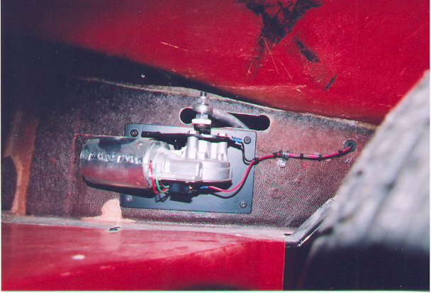
Photos: Ken Walsh The next several pictures show the installation of the pantograph windshield wiper assembly I selected for my car. It's actually a unit designed for marine use, and can be found in the on-line Marine Parts catalog (www.marineparts.com). The particular unit I picked was called the WWJ series. I'm certain there are other on-line sources, as well--just browse under "pantograph wiper" and see what pops up. I installed the motor assembly in the passenger wheel well, just above the start of the side pods. I used "one-half" of the mounting bracket supplied with the assembly--the part that actually bolts to the wiper motor. I completed the bracket by welding a large square plate to the supplied bracket. This plate, in turn, is bolted to the fiberglass. Although this is a small motor, the worm drive reduction on it generates plenty of torque, so using a large plate helps distribute the torquing load over a larger surface of the fiberglass. At the top of the motor assembly, you can see a rod end and a shaft--this transmits the wiper movement to the arm itself. (The hold cut in the fiberglass will be cleaned up, and a rubber gasket will be applied for cosmetic reasons.
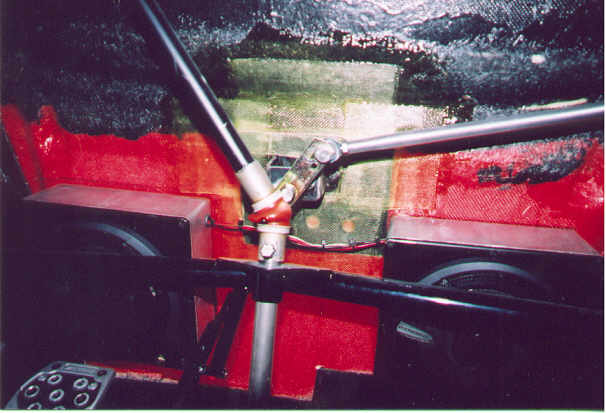
This picture shows the actual wiper pivot. To orient you, this pic was taken from the bottom of the footwell, looking up; the bottom of the pic is the front of the car; the rear is towards the top. The two aluminum and black "boxes" are baffles for my loudspeakers, bonded with epoxy to the underside of the nose. The shaft extending from the bottom of the pic is my steering shaft (the Porsche rack and pinion takes the steering shaft at the center of the steering box). This shaft goes through the Apex joint, and traverses to the upper left, and the steering wheel. Under the Apex joint (above it, in reality) is the mount for the wiper arm. I fabricated a U-shaped bracket, and welded it to to steel plate. Also welded to the steel plate is a bolt that is used to serve as a pivot point for the "slave arm" of the pantograph (see later pic). This steel plate was 'glassed into the existing fiberglass, just below the juncture of the windshield.
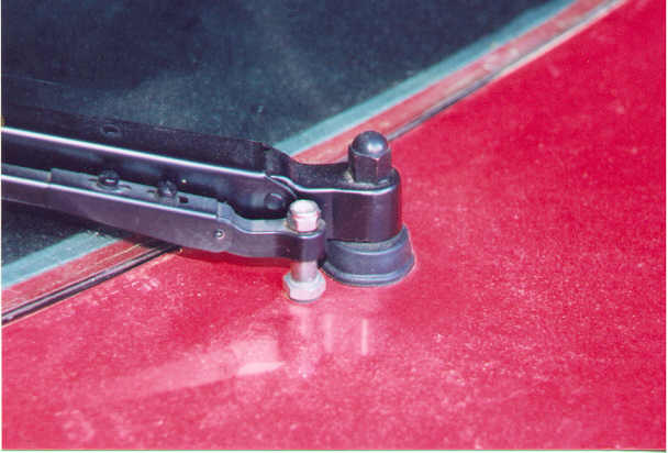
Here's a view of the "topside" of the mount. The mounting hardware for the driven arm is supplied with the kit; The slave arm hardware is predominantly a bolt (welded to the mounting plate under the body), and spacers; a nylon stop nut completes the installation (ultimately, I will paint this stuff matte black, to match the other parts of the arm.
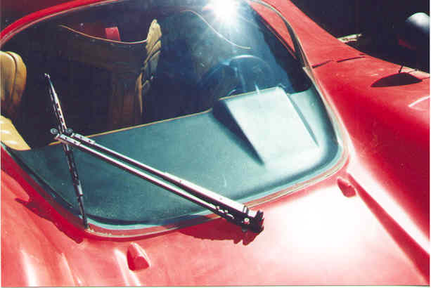
OK. Here's the final product. It works extremely well--has great windshield coverage, and auto-parks at the extremity of travel on the passenger side. It also has nice "bling bling" appeal. Even under max torque conditions (almost dry windshield) the movement is solid, and there's no flexing at the motor or arm mounts.
All that I need to down now, if figure what to do with the two original Mirage bosses for the dual wiper system. One option is to install two windshield washer nozzles on them. The other option is to "glass 'em over" and remove them. * * * *
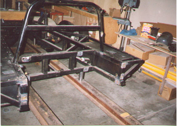
A number of folks have asked about the transition of the stock Mirage rear to my current configuration. As you might imagine, that was my first major undertaking in the rebuild of my car, and it's laborious, but not all that difficult. The first part is easy--but it takes courage! This is the rear of the stock Mirage chassis, after stripping the stock Chev V-8, Corvair transaxle and suspension--and after spending five minutes with a "Sawz-all" (a few beers beforehand help prepare for this major surgery).
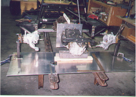
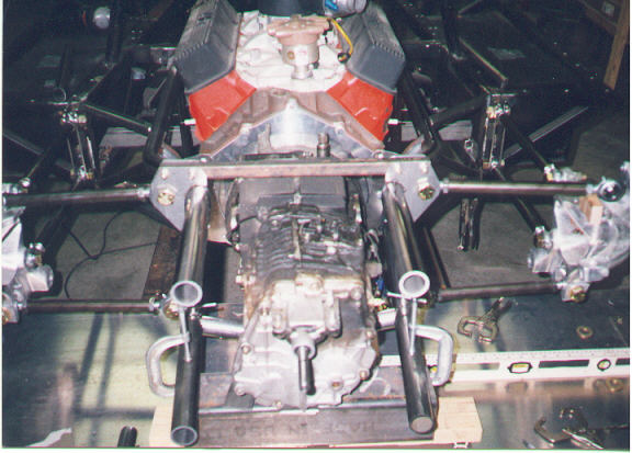
With the trauma overcome, the next step is to true-up the chassis on a stout build table. You can see the I-beams used to hold alignment of the chassis for all the follow on work. It's important everything is measured two-three times before cutting anything, and that you tack weld as you go (don't final weld anything yet--believe me!) In addition to the build table beams, I also used plate aluminum and additional under table supports to keep everything in line. Here, you see the next major step--acurately aligning the two rear Corvette uprights. This location is critical for the remainder of the build--and for having a car that faithfully goes where you point it. The dimensions for the rear upright locations are replicated from the original suspension points for wheelbase and wheel track (you need to consider tire width, wheel setback, etc, as you do this. Once you loate the uprights--measure everything three times more, to include diagonal measurements from each front wheel hub to the opposite rear one. Geometry and alignment are vital. Also note I've placed the engine (mule) K.E.P. transaxle adapter and the transaxle into the chassis cavity--just to make certain all major dimensions will fit.
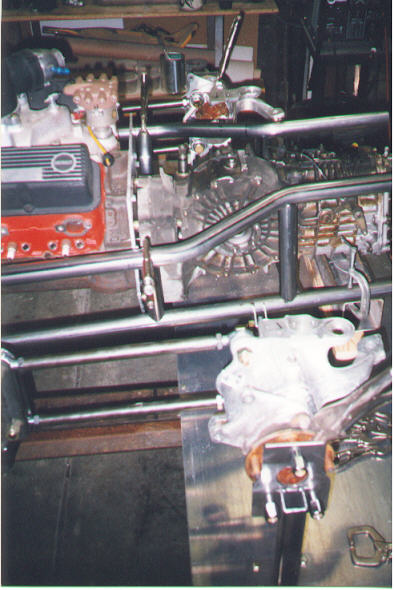
In the next photo, the first work done was the two upper and lower radius rods that locate the Corvette uprights for the proper wheelbase. You'll also notice the start of the custom bracketry for this conversion. While the overall conversion takes time, the brackets were really time-consuming, to get them right, and well groomed. This is where "detail work" pays off in the end. You can also see the basic engine cradle taking place. This tubular assembly holds the engine, transaxle, and serves as the mounting point for all the lateral suspension points. Again--tack weld only at this time. I did most of this work with "mental plans"--envisioned what I wanted to do, and had a few sketches for me and my friends to work against. When you consider the wheelbase, track, suspension geomentry,and engine-transaxle dimensions dictate most everything else, you go from there. If you notice the 1/4" aluminum plate just to the rear of the transaxle adapter (bellhousing area), this becomes, after cutting a major mounting point for the engine, along with the front motor place (photo further down).
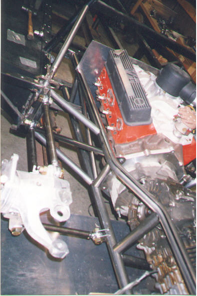
The following picture shows the start of the chassis triangulation. Believe me, this thing is stout, and while I used mild steel, it's not overly heavy. WIth the torque of the twin-turbos and fuel-injection, a relatively rigid chassis was needed to fight handling problems. You can also see the fabrication of the first lower radius rods, that locates the Corvette upright from the transaxle mount. The radius rod tied nicely to the lower Corvetter mounting point. The other end required more custom bracketry on the new tube chassis. You can also see the front 1/4" aluminum plate, that supported the engine during the build--and that ultimately became the tooled front motor mount/plate.
Here is the start of the fabrication of the rear "suspension hoop" that's tied to the new chassis, as well as providing the inner pivot points for the upper transaxle-upright radius rods. More custom brackets. If you note, there's more custom bracketry attaching these upper radius rods to the Corvette uprights--GM wasn't nice enough to provide these mounting points, so they had to be custom made brackets. In hindsight, billet pieces would have been nice, but the ones made from steel plate aren't too shabby, in any case! Most of the major chassis work is coming together, except for the final bracing at the rear of the Porsche transaxle (yep, it's inverted), and the coil-over mounting points. At this point, I also had to start seriously considering all the plumbing for the twin turbos and the intercoolers, oil lines, linkages, etc. (Did I mention everything is just tack-welded together at this time???)
This is a photo of the front motor plate, after it's been cut. I later gave this a light bead-blasting and clear anodizing. I think it looks pretty "authoriative". I haven't mentioned the engine and transaxle are all solidly mounted to the chassis--no rubber mounts. While this means your butt is very closely attuned to every engine vibration and torque loading (is this bad?) it also means no problems with rubber mounts on a 1,000 HP high-performance car. I'm willing to forfeit the creature comforts (gees, I don't even have air-conditioning in this monster!)
This is a view of the new rear deck struts, necessitated by "chopping" the rear of the Manta body. A body-wide 1" x 1" square rail was 'glassed into the body. Round tubular Y-shaped struts were fabricated to run from the chassis to the new body mounting points. These Y-shaped struts, with rod ends at each extremity, control the up-and-down and the left-and-right alignment of the body. Both the Y-struts and the new body rail are strong enough to take the modest downforce loads I expect the rear wing/spoiler to generate at speed. Two smaller struts, also with rod ends extend from the Y-struts to additional 'glassed-in mounting points that set the fore-and-aft body alignment. The two wire-rope supports hold the deck when in the open position--these are temporary, until I design the electric jack-screw system to open/close the deck from the cockpit.
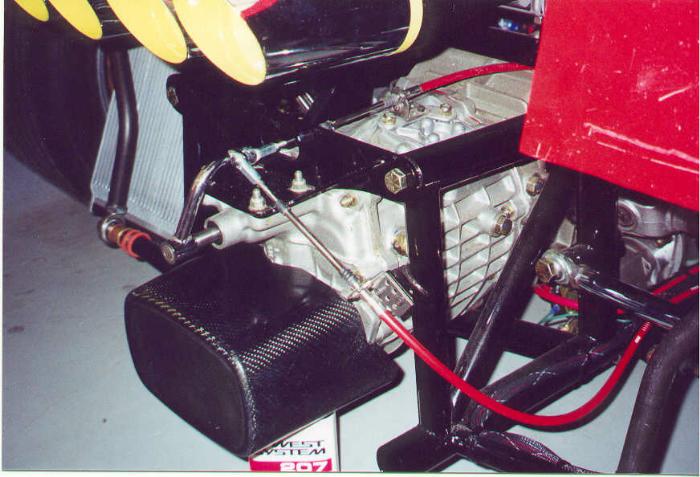
Another close-up view of the rear of the transaxle, showing the snubber in more detail (final fitting had yet to be done). The carbon composite "texture" is definitely visible (I love this stuff!). A number of folks have asked about the cable shifting mechanism. I using a shift mechanism from an unknown Japanese "donor car", with 12' long Morse cables, and custom shift rod (chromed, in the picture) at the rear. All internal gates in the shift lever mechanism have been removed--all shift positioning is controlled by the internal Porsche transaxle shift rod indexing, and reverse lock-outs.
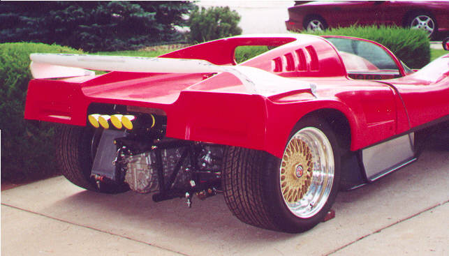
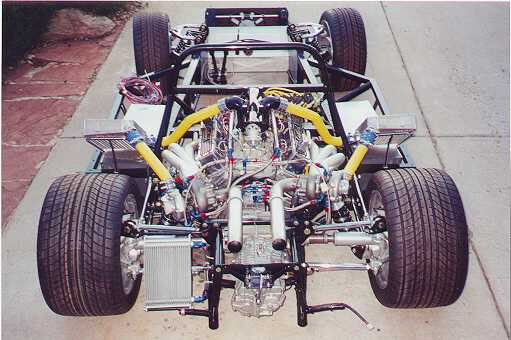
A view of the rear of the car. Visible are the two new deck struts to hold up the rear body work (more details, below). Also visible is the inverted Porsche 930 transaxle and the cables associated with the cable-shift mechanism. To the driver's left of the transaxle is the oil cooler. The rear body section has been "rough cut" and will be finished when I finalize the body design. The two dual exhaust silencers are also shown. At the rear of the transaxle, I've added a "snubber" styled after IRL cars. On these race cars, these snubbers reduce G-force impacts on accidents when cars back into walls at speed. In my case it might help reduce minor accident impact (although it's largely cosmetic--too low for most car-to-car contact). It's carbon fiber and epoxy resin--the "casting" was done in a very inexpensive mold (go to K-Mart, and buy a plastic wastepaper can for about $3.00).....! In this photo, it's location is mocked up. The snubber is now mounted on standoffs to the transaxle. Job complete.
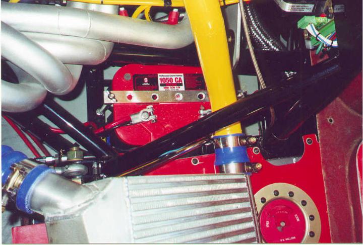
The area below the right-side cylinder head is nothing exotic--just a large-capacity Optima gel-cell battery. The battery is mounted on a tray that can be unbolted from the chassis rails, and removed from below the car. This permits the best possible access to the battery, considering all the other plumbing above it. Again, this might be an area requiring more off that nifty carbon-composite material to shield heat from the battery. I'll get back to you, on that one.... not my highest priority right now.
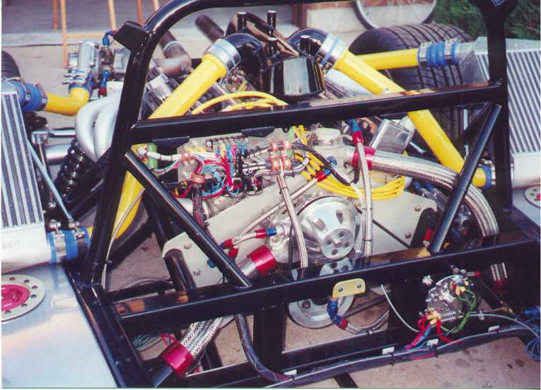
Some folks have asked where I've hidden the pumps, etc for the engine. This is a view looking downward below the engine's left cylinder head. Attached to the old Manta frame are two parallel Fram oil filters (I have to use "shortie" filters due to space constraints). The filters are used with a remote filter adapter on the engine block, and a rear-mounted oil cooler. Below the filters are the two Bosch electric fuel pumps. I run about 50-60 PSI pressure, and the two pumps can provide enough fuel flow for 1,200 horsepower. Fuel flow goes from the two Manta saddle tanks into one pre-pump fuel filter (mounted behind the driver-side saddle tank, inside the lower body panel). From there, the fuel goes to the two Bosch pumps in parallel, then each pump goes to an individual post-pump filter (mounted just to the rear of the two pumps), and then to the left/right engine fuel rails. The fuel rails provide gas to the injectors, and then are routed to a common pressure regulator. The regulator maintains the pressure in the fuel rails, and routes "surplus fuel" back to the Manta saddle tanks. Lots of plumbing. Lots of opportunity for leaks (sigh...).
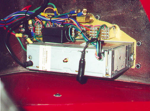
This is view of the Electromotive TEC II engine controller. It's great--permits infinite tuning of the engine, and eliminates the distributor-based ignition system. It is programmed via an IBM-compatible PC. In addition, when the engine's running, I can download real-time data on all vital engine functions to assist in tuning. In this photo, the connectors for the input data (manifold pressure, throttle position, exhaust oxygen sensors, manifold air temp, etc) and the output data (injector commanding, high-voltage ignition, tach output, etc) are shown. Below the TEC unit are four Bosch relays, that control the high current demands of the two Bosch fuel pumps and the injectors. I still plan on fabricating a carbon-composite heat shield to deflect hot air flow from the headers, to help keep the TEC running cool. To date, I haven't had a heat-related problem, but any opportunity to use carbon-composite (looks neat!) appeals to me.
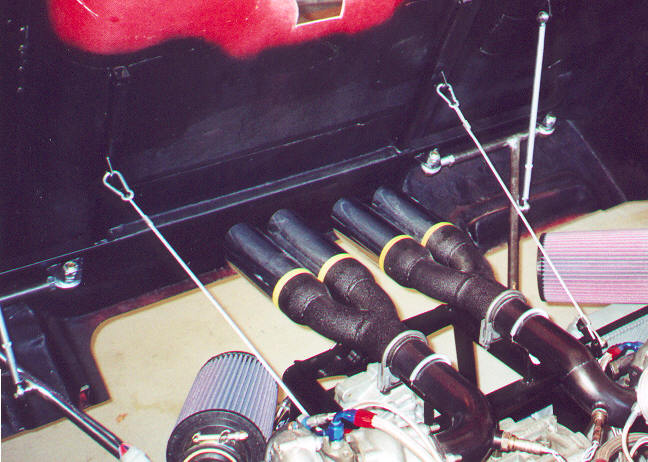
I've gotten a number of questions regarding turbo plumbing and boost controls. Here goes. The two GM throttle bodies are mounted vertically on the 2 x 4-barrel intake manifold. The front unit retains the idle-air control motor. The rear one has the IAC motor removed, and air passages plugged. The plenum above the throttle bodies is hand-made. At the extreme rear of the plenum (over the bell-housing) is a turbo compressor by-pass valve (it's mounted at the 45 degree angle). When the driver lifts off the throttle, and the throttle bodies close, the turbo pressure traditionally would "back up" in the plenum, duct work, and intercooler, and then cause enough back pressure to significantly "spin down" the turbos. When the driver goes back "on the gas", the turbos then have to spin back up, before providing adequate boost. This is the dreaded "turbo lag" problem. The compressor by-pass valve has a sensing line (at the extreme end of the valve assembly) that detects a closed throttle condition (vacuum in the intake manifold) and then opens the plenum to the surrounding air. This reduces the back pressure to the plenum and turbo, and keeps the turbos spun up. (And the sound of the by-pass "hissing" is very attention getting!). It works wonders for responsiveness and acceleration. SARD makes the valve. A few inches in front of the by-pass valve, visible here, is a small horizontally-mounted air valve, controlled by the Electromotive TEC engine controller. This valve is energized at a preprogrammed boost level (adjustable via a PC or Laptop), and when opened, passes boosted plenum air through the valve, to the small one-into-two block below the compressor by-pass valve (this is actually a fuel block that has been pressed into service, here). The two outgoing braided steel lines go to the two turbo boost bellows, which operate internal boost wastegates in each turbo. In this way, the turbos provide full power (no early opening of the wastegate) until the TEC senses maximum boost, opens the small air valve, and then the bellow go "full open" to open the exhaust wastegates. This maintains full turbo pressure until the TEC commands otherwise. Lot's of plumbing, but the result is worth it. Having a fully programmable boost control is nice, particularly when first tuning (and first driving!) an aggressive turbo engine.
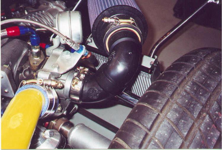
Sometimes, you just go with "what's easy". I had initially envisioned using large triangular foam-and-chrome air cleaners on each turbo, and fabricating carbon-composite intake ducts between the cleaner and turbo. I then reconsidered, and went with the more contemporary K&N filters. The only problem--how to fabricate ducts. Shown here is my solution--custom ducting from high-impact thermoset injection-molded plastic air conduits. (Or, to put it another way, about $5.00 of black plastic sewer pipe from the local hardware store....!). Inexpensive, readily available, and suitably high-tech looking. I was able, after some juggling, to use 45 and 90 degree elbows and straight segments to get the two filters perfectly aligned and symmetrical. Like I said, sometimes you just go with what's easy...
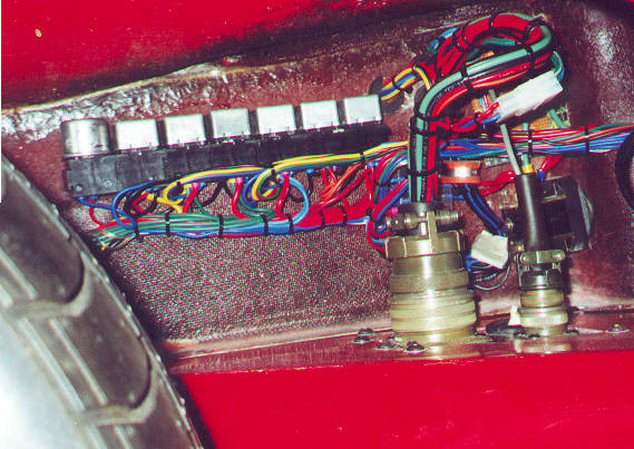
A few of the main power control area, tucked into the driver's wheel well area. A carbon-composite "gravel shield" is being molded to cover this area, and the instrument panel backside. The only down-fall in using the computer switches on the instrument panel is that they are made using low-power capacity microswitches. As such, I require relays (energized by these switches) to handle most of the power needs for the lights, fan, horn, etc. You'll also see two Cannon-type connectors used in the wiring harnesses. These pass all electrical functions between the front of the car and the remainder of the chassis. The large connector passes all battery, switched, gauge and data functions. The smaller connectors provides separation for the speedometer sensor low-voltage signal. The only other "mechanical connections" between the car's nose and the chassis is the turbo vacuum/boost hose and the steering shaft. By disconnecting the wiring harnesses, one u-joint in the steering shaft and a quick fitting on the boost hose, I can remove the nose of the car in about three minutes. Nice feature....
Here's a rear view of the instrument panel. All wiring is done with quick-connect cable connectors to permit removal of the entire instrument panel intact. Wiring the entire car was time consuming but not a challenge. The only "problem" was when I first attempted to fire up the system. Everything was dead--no power, anywhere. I trouble-shot the whole mess for about 20 minutes--then I remembered to turn off the "kill switch". After that (duh) everything all worked perfectly. Yep, that kill switch really works fine....
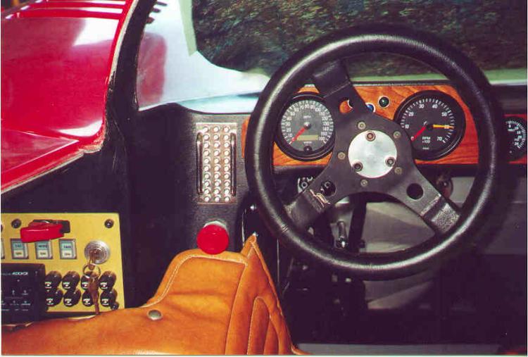
This is a shot of the instrument panel, mounted in on the wheel well wall, under the driver's door. Everything is visible to the driver, as you'd hope. The "race look" was borrowed to place all fuses in easy reach of the driver or potential pit crew guy. A hooded momentary-contact toggle switch is used for the starter. Horn push button and turn indicator toggles are also on the top row. The next row of ratchet-on switches were salvaged from an IBM main-frame computer (having a local salvage store here in town is very handy!). These switches include two internal lamps--the upper portion in each switch is illuminated when I have the Parking lights turned on (shows the function), and the lower portion is illuminated when that switch is turned on. Disregard the labels (also internal to the switch cover), which were used on an earlier car build-up (I will re-label the switches, in due time). The AM/FM/CD unit works great. The speakers are 8" units mounted in small infinite baffles in above the drive and passenger foot areas.
Another view of the "business end" of the passenger compartment. The speedometer is a VDO electronic, programmable unit. I "drive" it through the anti-lock braking front-wheel sensor that came with my Corvette suspension parts (slick, huh?). The darned thing actually works! The tach is also VDO. The center of the Grant steering wheel is a home made adapter to mount to the quick-release hubset. To the left of the wheel is a 30 LED multi-color "barber pole" display. The first column provides green/yellow/red indicators of fuel-air mix in the left cylinders (employs analog data from the exhaust's O2 sensor). The second column of LEDs does the same, for the right-hand cylinders. The last column of LEDs provides green/yellow/red indicators of injector "turn on" times (if I exceed 90% duty factor, I know I'm putting out gobs of horsepower--and if I do it consistently, I might need to go to bigger injectors). Below the LEDs is a large "kill switch". Pressing it in removes all power from the car. (If anyone else is running EFI, with fuel under lots of pressure, I recommend you consider doing the same, in case a hose or fitting lets go). The use of this kill switch was borrowed from some of the IMSA cars I've seen racing recently. Disregard the loose-fitting upholstery, though--this is only a trial fit, for now (and in case you're wondering this IS the original Manta upholstery package, in the same colors as Brad and Tim's showroom car, that's been unused for the last 22 years!).
Here's a view of the dash, in a not-fully-finished state. The dash itself is 1/8" cherry with recessed VDO gauges. The steering wheel is a Grant unit, and uses a quick-disconnect hub. Nothing too exotic here.
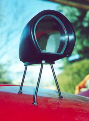
Some folks have asked me where I got the rear view mirror assemblies. They're home made. They consist of a Talbot racing mirror design (the passenger's side is convex for greater viewing area). The mounts are 1/4" aluminum plate, with steel rods threaded and tapped for machine nuts. It's simple and sanitary--and I recall seeing some of the Can-Am marques using similar set-ups back in the "good old days" of real car racing.
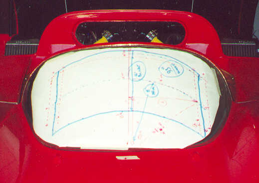
I've been looking for a "different" windshield wiper solution for the Manta, and I think I might have found it. I've located a marine unit (sold at www.marineparts.com) that provided a "pantograph" wiper assembly, complete with motor drive. With the pantograph system, two wiper arms are used, keeping the blade vertical throughout it's travel. The unit (identified as a WWJ model) has adjustable speeds, sweep range, arm length and blade length. Show here is the mock-up of the units coverage, assuming a centerline mounting, and using the 93 degree sweep, 18" arm lengths and 16" blade. I've received the WWJ unit a few days ago--it's well made, looks "hefty" and should complement the look of the Manta. I'm going to mount the motor drive assembly in the passenger-side wheel well, and use a pushrod assembly with adjustable rod ends to control the wiper arm.
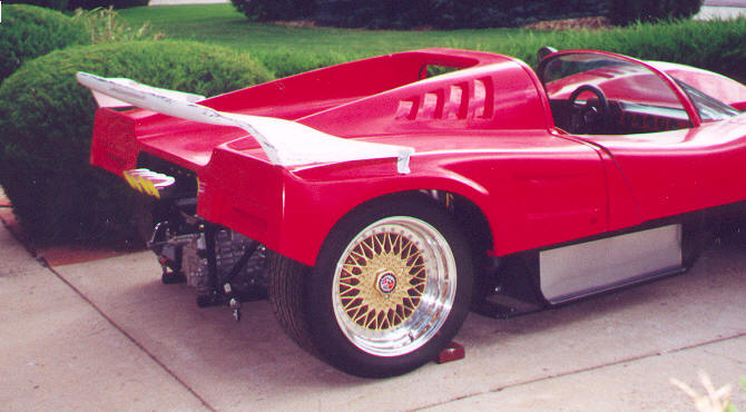
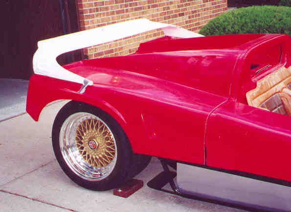
All the wiring is done, and all the minor coolant, lubricant and fuel line (EFI high pressure!) have been attended to. I did my first "in-chassis" engine cranking last week. As soon as I am able to program the Electromotive TEC EFI/ignition computer on board, I will be going for my first spin. I'm trial fitting body sections now. I took my previously unmolested Manta body and (gulp...) sectioned the rear, to ultimately update the body style. In these three photos, you'll see the rough idea of where I'm going. I rough-cut the fiberglass and internal deck supports. I'm currently fitting the tail lights, 'glassing in new rear panels on each side below the lights, and then will re'glass in the "rolled bottoms" of the original Manta design. (In old "hot-rodder terms", I effectively took about a 10 inch "section" out of the rear panel. When it's all reglassed, I'll send another update. The wing is a 72" wide "Texas Tail" that fits the Mirage body just about perfectly. I will build up two hardwood pylons and glass them into the body, to hold the wing in position just about where it's shown in the photos. The quality of the 'glass of the wing was probably OK for it's original use (a pick-up truck!), but I will do a lot of fit and finish before I'm content with it. All told, it's a great look for the sectioned rear, and with the chopped back it gives the old Mirage a newer IMSA look.
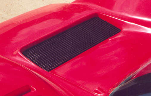
You might find this idea interesting..... I've seen a lot of guys using flat stamped grill material or expanded metal for the nose air intake and the radiator duct outlet. I'm using material designed as overhead flourescent light grille "diffusers". It has more depth than stamped material, it's lightweight, and it's easy to cut/machine. In a pinch, you can even fasten it with cable ties. I painted mine with a matte black, to match the chassis and interior body color. Racing improves the breed--so does home construction!
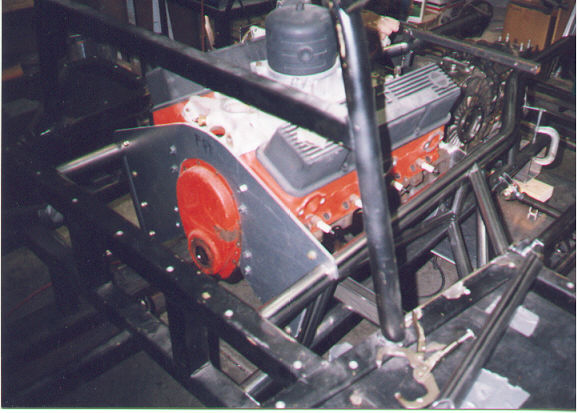
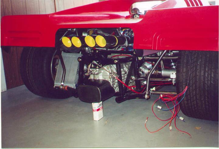
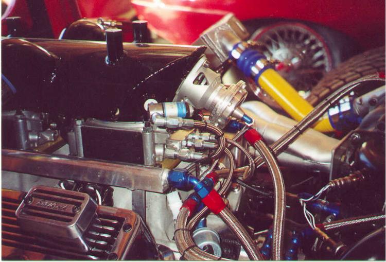
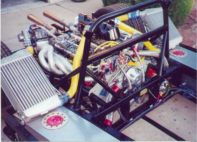
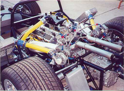
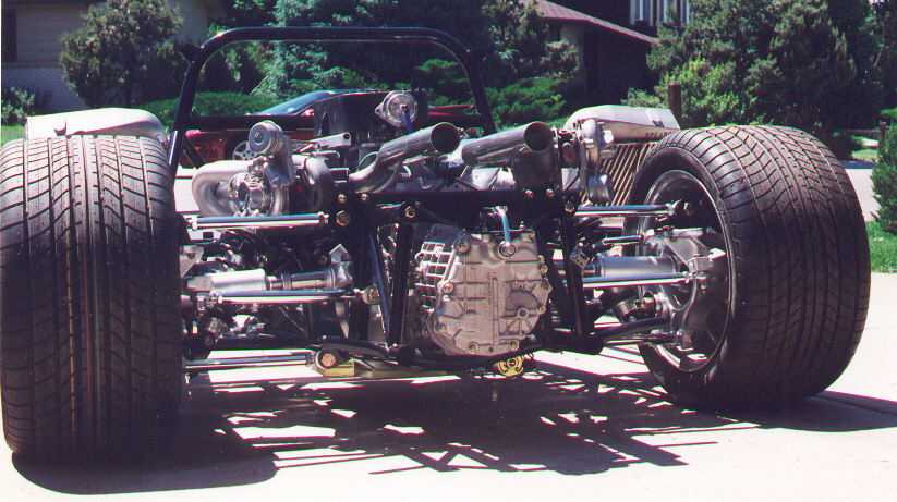
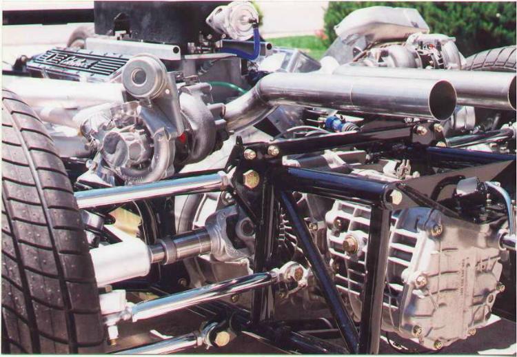
The stock Mirage chassis was removed at the roll bar area and everything was custom built for the suspension, engine and transaxle mounts. Nore the engine plate for the front engine mount--all cut and machined from solid aluminum plate. The headers are also built from scratch--a friend did them, and he's an artist with a TIG torch. The alternator was reverse mounted, for clearance (normal mounting area below driver-side cylinder head is used by two Bosch electric fuel injection pumps and three large fuel filters. Two tandem remote oil filters are also in the same aarea. Intercoolers are Spearco. On a dyno, the 355 cu in engine max'ed at 1143 HP, at 6,200 rpm. Will be backed off on the streets, to save the Porsche 911 Turbo (930) transaxle (about 750-800 hp, max). Kennedy Engineering Products did the engine-transaxle adapter, and I'm using a multi-plate composite material clutch. The engine uses twin stock GM throttle bodies (circa 93 Trans-Ams) that can flow 1200 CFM together. They mount on a modified Offenhauser twin 4-barrell carb manifold; the manifold was also modified for individual cylinder EFI nozzles (72 lbs/hr each), running a 65 psi, but "boosted" by the fuel pressure regulator (that senses turbo boost pressures and raises fuel rail pressure accordingly, up to 90 PSI under full turbo boost). Partly visible is the compressor surge by-pass valve at the rear of the homemade air plenum--under closed throttle conditions, this valve opens and vents plenum air pressure (allows the turbos to stay "spun up" under engine deceleration). Note that there is no distributor over the bellhousing area--the Electromotive TEC energy management computer operates the EFI injectors, and also provides direct fire ignition with 4 individual coils. The TEC is a great unit--infinitely "tunable" for all engine conditions--and I even use it to open the turbo wastegates under boost limiting (avoids standard bellows operated wastegates, that tend to crack open prematurely before max boost conditions).
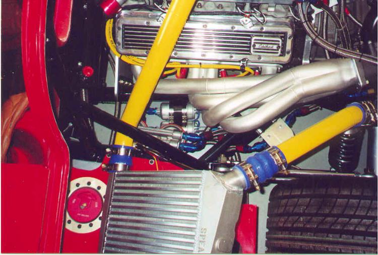
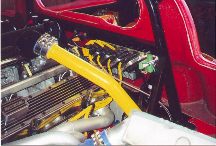
....another view of the engine, clearly showing the engine mount plate and the homemade air plenum and intercooler ducting. This has been a VERY slow build up; lots of design work, before fabrication, and then slow and deliberage selection of just the right parts. Finding just the right silicone hoses and clamps for the turbo plumbing took more than three weeks.... The Electromotive TEC EFI/Ignition computer is mounted on the square horizontal member of the roll bar (just behind the passenger's head....). >From this photo, you see the REAR of the computer--that's where I've hidden all the wiring and fuses associated with EFI energy mangement (all the sensors, fuel pump electrics, injector leads, etc). On, yeah... almost $2,000 in braided steel lines (everywhere!). Earl's Competiton Products guys have gotten to know me very well!
I'm also adding (believe it or not....) a "Texas-tail" wing designed for a full size Ford pick-up truck complete with third brakelight. I had studied this one for about two months before I found what I wanted. Finally boiled down to be flagging down(!) a pick-up truck on the Interstate, when I noticed they had exactly what I was looking for. Fortunately, the driver understood, and was able to give me the name of the supplier. This wing will definitely look "trick" on the cropped rear.
|
|